Mechanical, Electrical, and Plumbing systems are the nerve centre of every project. When they do not coordinate perfectly, it disrupts budgets, timelines and even client relationships. The solution is a well-structured MEP BIM workflow. MEP always starts as a rough idea and passes through dozens of hands, revisions and coordination checks before being installed on site.
A 2025 European analysis found that 12 EU countries have introduced some form of legal BIM mandate for public projects. Many others have established national BIM strategies, standards or implementation roadmaps — SOURCE
AEC professionals must understand how design intent transforms into buildable shop drawings, not just as useful background knowledge, but as a way to ensure a smooth handover. At Tesla BIM Services, we have spent nearly two decades helping project teams achieve this process. Let’s take a look at how the complete journey of MEP BIM unfolds, stage by stage.
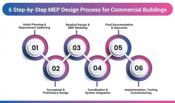
A successful MEP BIM project follows a structured workflow that connects planning, design, coordination, documentation and construction – helping teams deliver precise models and better building outcomes.
It Begins with Design Intent
Design intent is the starting point of any MEP project. Consulting engineers produce conceptual layouts, such as duct runs, pipe routing and electrical distribution, in schematic form, typically at LOD 100-200. The goal is decision-making, not precision.
Once the conceptual layouts are complete, they are overlaid with the building’s structural and architectural drawings to identify any conflicts. These are then resolved before the project moves to the next stage.
Translating Intent into a Coordinated 3D Model
Once design intent is final, the next step is to build it out as a federated BIM model in Revit or Navisworks. Mechanical, electrical, plumbing, and fire protection are all modeled separately and then combined into a single coordinated environment. All the models contain accurate geometry, correct equipment sizes and proper connectivity, reaching LOD 300.
This federated model is now ready to detect any clashes, overlaps and other spatial conflicts between the different systems.
A 2025 European Public Buyers Community survey reported that more than 75% of respondents rated national BIM mandates as ‘important’ or ‘very important’ to increase the use of BIM by their citizens — SOURCE
Clash Detection: Catching Problems Before They’re Expensive
Clash detection is the most valuable stage of the workflow. With software like Navisworks or Solibri, all models are merged and checked for hard (physical overlaps) & soft (insufficient clearance space) clashes.
An infrastructure case study, published by Northumbria University, demonstrated that BIM-enabled clash detection saves almost 20% of the project’s contract value by identifying and resolving design conflicts before construction — SOURCE
Clash detection helps contractors avoid weeks of rework while reducing material waste and associated costs. For architects, it helps protect overall design aesthetics from being compromised by unresolved service conflicts.
It is important to note that clash detection is an iterative process, carried out at every stage of design development and drawing revision.
Clash detection reports list conflicts by priority, so teams know what to tackle first.
Coordination Meetings and Model Refinement
Once clashes have been identified, the relevant project teams meet, either virtually or in person, to review and resolve the conflicts. This coordination process takes place over multiple rounds, gradually refining the model from LOD 300 to LOD 350, with accurately sized systems and fully coordinated structural and architectural elements.
This model now becomes the single source of truth for construction and installation. Contractors can make schedules, estimate material quantities and plan the site process with its potential issues before even stepping foot on site.
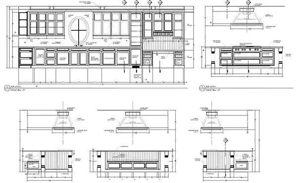
Source: https://purplecherry.com/
Generated directly from coordinated BIM models, shop drawings give contractors the detailed information they need to reduce errors, improve accuracy and keep projects on schedule.
With the model coordinated and approved, you can now extract the shop drawings. These are detailed and trade-specific documents that fabricators, contractors and installers can work from on-site.
Plans, sections, details and isometric views of these drawings include:
- Detailed routing plans, with exact dimensions
- Equipment schedules and manufacturer specifications
- Connection details, interface references
- Installation sequences & phasing information
- Clearances & tolerances
These drawings are developed at LOD 400, where accuracy is essential. The drawings are fully aligned with the BIM model, ensuring there is no discrepancy between the two.
Fabrication-Level Detail (LOD 400)
For projects with prefabrication, the workflow extends to LOD 400 with complete fabrication detail. Models will include manufacturer-specific data like part numbers & welding specifications. Spool drawings are also made for off-site prefabrication of pipework and ductwork assemblies, making on-site installations faster with less labor.
Quality Checks before Site Delivery
A structured quality assurance process is mandatory before any drawing reaches the site. At Tesla BIM Services, every deliverable undergoes a two-step process. The first is an internal technical review. This is followed by a client-facing validation against the project’s standards, specifications and requirements.
This process helps identify and resolve issues such as missing annotations, incorrect dimensions and coordination gaps before the drawings are issued for construction.
Supporting Installation and As-Built Documentation
The workflow doesn’t end at shop drawings. After installation and construction, on-site changes have to be documented back into the model to create an LOD 500 as-built model and drawings. These will later be used for facilities management and future renovations.
Bringing It All Together
From design intent to shop drawings, the journey isn’t linear. But it doesn’t have to be chaotic. With a structured BIM workflow, architects and contractors can avoid the delays, rework and unnecessary costs caused by poorly coordinated MEP systems.
The formula is clear: consistent modeling standards, disciplined clash detection and rigorous quality checks. Fragmented 2D drawings are replaced with a data-rich 3D environment.
At Tesla BIM Services, we help clients navigate BIM modeling, MEP coordination and shop drawing services tailored to your project’s needs. For architects, design vision is translated into installation – and for contractors, the project stays in budget and on schedule. A well-managed MEP BIM workflow is one of the best & most practical investments you can make in a project’s success.
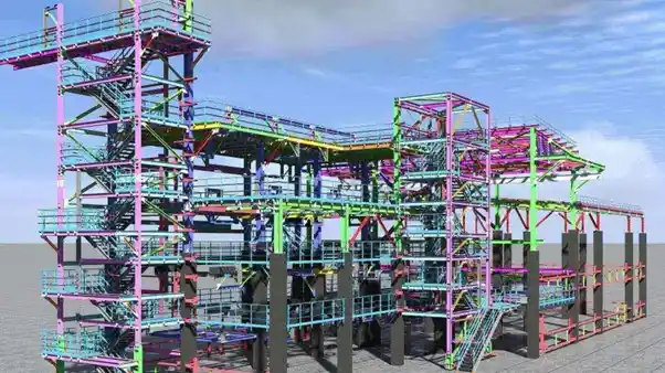
Instead of working in isolated drawings, project teams collaborate within a shared BIM environment where every update is visible, coordinated and aligned with the project.
FAQs
Is a ‘clash-free’ model enough to guarantee a smooth installation?
There are a few things that might make a clash-free model unbuildable, such as:
- Access space: for installation tools, such as pipe pressing equipment or welding gear.
- Joint positioning: The modeller may not have considered how pipework is fabricated and assembled in sections
- Missing support locations: for hangers and brackets
- Maintenance access: for damper servicing or future valve replacement.
Critical insight separates a good BIM model from a great one.
What happens to the BIM model after the building is handed over?
The BIM model’s job doesn’t end at handover. It becomes the foundation for how the building is operated and maintained. During installation, contractors often make small on-site adjustments that don’t exactly match the design model. These changes need to be captured and fed back into the model so it reflects what was actually built.
This updated version is developed to LOD 500, the highest level of detail, where the model and drawings represent the true as-built condition of the building. Facilities managers rely on this as-built model for day-to-day operations. The as-built model also becomes valuable for future work.
What is ISO 19650? Why does it matter for European MEP projects?
ISO 19650 is the international standard for managing information throughout a building’s lifecycle using BIM. It defines the processes, roles, and responsibilities for creating, reviewing, sharing, and storing project information. Mandatory for public sector projects in the UK, ISO 19650 is also being increasingly adopted across Europe for both public and private sector projects.
Aligning your MEP BIM workflow with ISO 19650 principles enables seamless collaboration within your clients’ Common Data Environments (CDEs).